You have a square or rectangular sheet of raw material. Maybe it’s steel, aluminum, or a piece of yellow construction paper. You need to cut a specific shape out of the raw material with wasting as little of it as possible. Maybe you get some cash back for selling the scrap material but it’s not as much as the raw material itself. How do you know what orientation of the part is best so as to use as much of the material as possible? Use the blank layout optimizer macro to find out what the best orientation is to maximize your material yield.
In this tutorial, you’ll learn:
- How to use extremum points in CATIA
- How to create parameters and link them to a measure
- How to automatically update CATIA measurements
- How to export CATIA data to Excel
- How to rotate a sketch with a CATScript macro
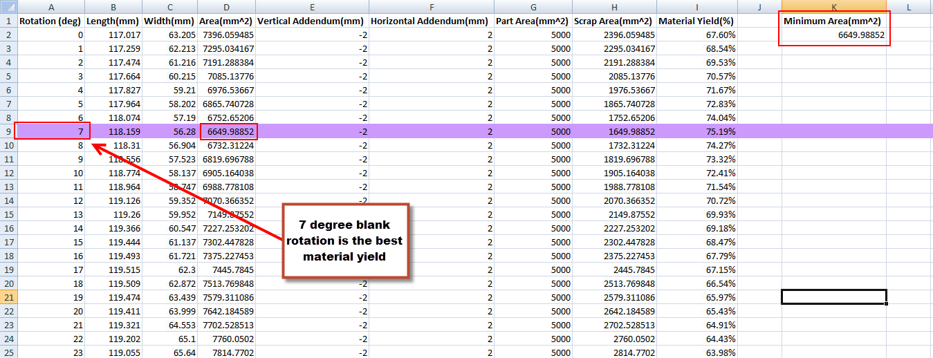
- How to highlight a row in Excel based on a cell’s value by vba
To see the end result to get an idea of what we are working towards, watch the video below:
Part One: Geometry Creation and Setup
Before we begin coding, we need to setup our CATPart template. Imagine unfolding a sheet metal bracket into a flat shape. That unfolded shape needs to be cut out of a rectangular blank sheet of steel before it is folded into its final shape.
- Create a new CATPart
- Create a new point at the origin (0,0,0)
- Create a new axis system at the newly created point ( z axis should match the compass z axis direction)
- Create a new sketch on the XY plane. This is your blank layout, so you could also use software such as FastBlank to generate your unfolded shape. In this example, I have just made up a shape (don’t ask me what the final formed version would look like).

5. Now create a rotate of this Sketch about the Z axis. You can leave the rotation at 0 degrees for now.
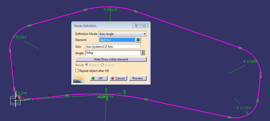
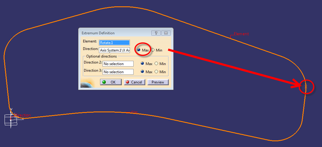
6. Next, in GSD under point, use the Extrenum tool to create four points that will automatically adjust when we later rotate this sketch.
![]()
The element will be your rotate. For the first point, direction will be X axis and use Max. For the second point, same thing except choose Min. Then repeat but change the x axis to the Y axis and do Max and Min for a total of four points on the furthest X and Y distances of the rotated sketch.
7. Create another sketch on the XY plane. This will be a sketch of our rectangular blank or starting material. Maybe it is a sheet of steel. Draw a rectangle. Constrain each side of the rectangle to each of the four extrenum points. You can make this distance whatever you want. In my case, I have linked the two y axis direction constraints to a “Vertical Addendum” parameter, and the max and min X points to a “Horizontal Addendum” parameter. When you rotate the sketch, this rectangle will also rotate and update automatically.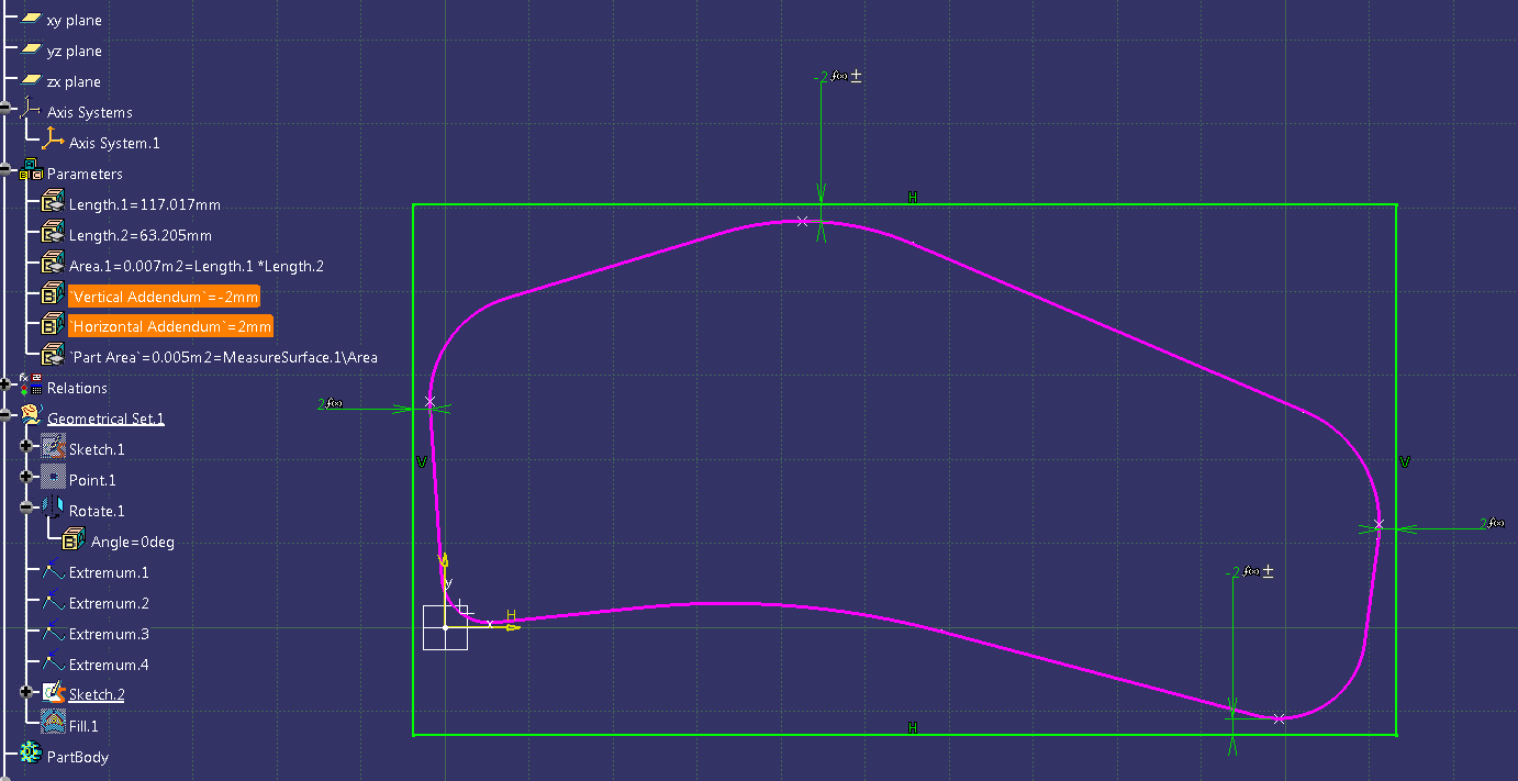
8. In order to compare area measurements later on, we need to fill in the sketch. Use the Fill tool.
9. Great! The geometry is finished. Now we need to add parameters and measurements. Create two new parameters for the length and width of the blank by clicking Formula then New Parameter of type Length.
10. Double click the newly create Width parameter. In the value field, right click and then select Measure Between.
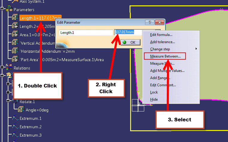
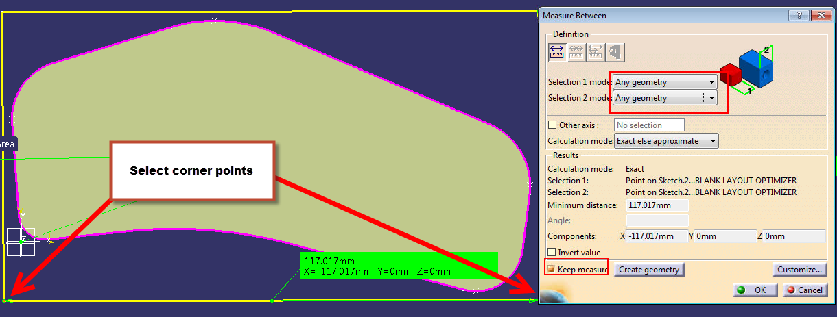
11. Select the two corner points to measure the width. Repeat this process for the length parameter.
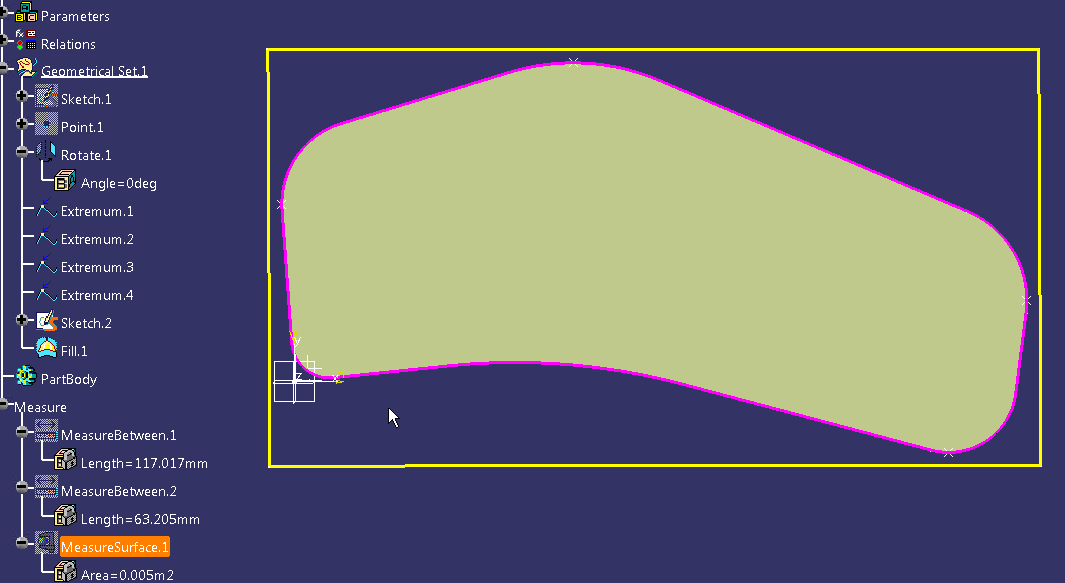
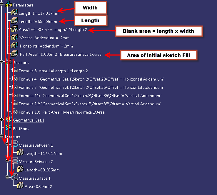
12. Make another parameter, this time of type Area. Create a formula to make the area equal to the length multiplied by the width parameters.
13. Create another parameter to measure the part area. Double click the parameter, right click in the value entry area and select “Measure Item.” Measure the area of the Fill you created earlier. Your final parameter and measure spec tree should look like this:
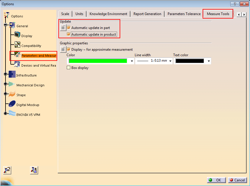
 14. It’s very important for the macro that you check this option before we continue. Go to Tools >Options>Parameters and Measure>Measure Tools. Under Update, ensure that Automatic update in part is selected. This is to automatically update the measurements that we just linked to the parameters. As the sketch is rotated, the rectangle will also update as will the length and width measurements.
Finally! Now our CATPart is setup and we are ready to begin the fun part – coding.
Part Two: Programming the CATScript Macro
Now that our CATPart is finally created and the geometry is all setup we can finally begin programming the macro.
- Create a new CATScript macro (or possibly CATVBA if you prefer)
- We’re going to spit out the results in Excel, so we’re going to need to launch a new session of Excel, a process I have explained here.
- Add our headers (top row labels) to the blank Excel sheet:
'--headers into Excel

Excel.Cells(1,1)="Rotation (deg)"

Excel.Cells(1,2)="Length(mm)"

Excel.Cells(1,3)="Width(mm)"

Excel.Cells(1,4)="Area(mm^2)"

Excel.Cells(1,5)="Vertical Addendum(mm)"

Excel.Cells(1,6)="Horizontal Addendum(mm)" Excel.Cells(1,7)="Part Area(mm^2)"

Excel.Cells(1,8) = "Scrap Area(mm^2)"

Excel.Cells(1,9) = "Material Yield(%)"

Excel.Cells(1,11) = "Minimum Area(mm^2)"

'Define the second row in the spreadsheet

Dim RowNum as Integer

RowNum = 2
4. Next, we’ll set the CATPart as the active document and define the rotation angle, which we’ll initially set at 0 degrees. If you run the macro and the rotate geometry is at 45 degrees, it will always change it to start at 0.
Dim partDocument1 As Document

Set partDocument1 = CATIA.ActiveDocument

Dim part1 As Part

Set part1 = partDocument1.Part

Dim hybridBodies1 As HybridBodies

Set hybridBodies1 = part1.HybridBodies

Dim hybridBody1 As HybridBody

Set hybridBody1 = hybridBodies1.Item("Geometrical Set.1")

Dim hybridShapes1 As HybridShapes

Set hybridShapes1 = hybridBody1.HybridShapes

Dim hybridShapeRotate1 As HybridShape

Set hybridShapeRotate1 = hybridShapes1.Item("Rotate.1")

Dim angle1 As Angle

Set angle1 = hybridShapeRotate1.Angle

Dim rotationangle as integer

rotationangle = 0
5. Now we’ll define all the parameters we made so that we can export the parameter data from CATIA into Excel later.
'---get the length, width, and area parameters-----

Dim parameters1 As Parameters

Set parameters1 = part1.Parameters

Dim LengthLong As Parameter

Set LengthLong = parameters1.Item("Length.1")

Dim LengthWide As Parameter

Set LengthWide = parameters1.Item("Length.2")

Dim oArea As Parameter

Set oArea = parameters1.Item("Area.1")

Dim oVert As Parameter

Set oVert = parameters1.Item("Vertical Addendum")

Dim oHorz As Parameter

Set oHorz = parameters1.Item("Horizontal Addendum")

Dim oPartArea As Parameter

Set oPartArea = parameters1.Item("Part Area")
6. The most critical part of the code is creating a For Next loop to rotate the sketch one degree, export all the measurement data, then rotate again, all the way from zero to ninety degrees.
'rotate the blank from 0 to 90 degrees in 1 degree increments

For i = 0 to 90

angle1.Value = rotationangle

'update all the measurements before exporting to Excel
part1.Update

'column A – show the rotation angle (will be a value between 0 and 90)
Excel.Cells(RowNum,1)= rotationangle

'Column B – show the length measurement
Excel.Cells(RowNum,2) =LengthLong.Value

'Column C – show the Width measurement
Excel.Cells(RowNum,3) =LengthWide.Value

'Column D – show the rectangle area measurement (length x width)
Excel.Cells(RowNum,4) =oArea.Value * 1000000

'Vertical addendum
Excel.Cells(RowNum,5) = oVert.Value

'Horiztonal addendum
Excel.Cells(RowNum,6) = oHorz.Value

'Part area – will not change
Excel.Cells(RowNum,7) = oPartArea.Value *  1000000

'calculate the scrap area (rectangle area – sketch area)
Excel.Cells(RowNum,8).Formula = "=D" & RowNum & " - G" & RowNum

'calculate the percentage of material used (the higher the better)
Excel.Cells(RowNum,9).Formula = "=G" & RowNum & "/D" & RowNum

'next rotation angle - one degree increments
rotationangle = rotationangle + 1

'next Excel row
RowNum = RowNum + 1

Next

'Find the minimum value for the best material yield
Excel.Cells(2,11).Formula = "=MIN(D2:D92)"
7. To make it easy to find the best blank layout orientation, we should highlight the Excel row that contains the smallest blank area value. Use the code below to highlight an Excel row based on another cell’s value.
'------highlight min row------

For j = 2 to 92


If Excel.Cells(j,4) = Excel.Cells(2,11) Then

Excel.Cells(j,4).EntireRow.Interior.ColorIndex = 39

Else


End if


Next
8. Finally, a few clean up and Excel formatting items, like bolding the header, centering the data in the columns, and auto-fitting the column widths.
'---Excel Formatting and Clean Up-------------

Excel.Rows("1:1").Select

Excel.Selection.Font.Bold = True

Excel.Range("A1:K92").EntireColumn.Autofit

Excel.Range("A1:K92").HorizontalAlignment = xlCenter

Excel.Range("A1:K92").VerticalAlignment = xlCenter

Excel.Range("I2:I92").Select

Excel.Selection.NumberFormat = "0.00%"

Excel.Rows("1:1").Select

Excel.Visible = True

End Sub
The final result should look like this:
Changing the addendum sizes will potentially yield different results. Again, here’s the end result you should see:
Now there’s no more guessing or trial in error in knowing what the best blank layout is. You’ll know exactly what the best orientation is in order to have the highest material yield. I hope you found this tutorial fun and useful!
To see other tutorials I have to offer, check out my page here.